
English 

Views: 0 Author: Site Editor Publish Time: 2026-11-15 Origin: Site


Incorrect pre-installation measurements often lead to severe operational consequences across industrial environments. A slight miscalculation can cause aggressive sheave pinching. It can trigger rapid core crushing. Ultimately, it results in catastrophic equipment failure during critical lifts. Installing an improperly sized rope creates massive, immediate business risks. You void manufacturer warranties instantly upon improper installation. You also trigger costly safety compliance violations during regulatory audits. Safety bodies demand strict adherence to sizing guidelines. To protect your operations, you must verify dimensions accurately before use. This guide establishes a rigorous, field-tested protocol. We focus on verifying rope diameter against expected tolerances. You must perform this verification before applying any tension to the system. We detail the exact steps needed to secure a proper baseline. You will learn how to select the correct measuring tools. By following this guide, you can avoid premature wear and ensure your equipment operates safely.
Measure across the crowns: True diameter is the circumscribed circle, never the distance between strand valleys.
Use appropriate tooling: Flat-jaw vernier calipers are the industry standard; standard calipers often yield false undersized readings.
Factor in manufacturing tolerances: New steel wire rope is typically manufactured slightly oversized (never undersized) to account for initial stretch and seating.
Average your readings: A single measurement is insufficient; compliance requires multiple measurements taken at varying angles and locations.
Skipping pre-installation diameter checks creates massive operational risks. Sheaves and grooves demand precise dimensional compatibility to function safely. When you run oversized ropes through undersized grooves, they suffer immediate crushing. The groove pinches the outer wires forcefully during operation. This pinching destroys the structural integrity rapidly. Wire fatigue accelerates under these heavily pinched conditions. Conversely, undersized ropes flatten out inside oversized grooves. They lack proper sidewall support. They lose their cylindrical shape rapidly under heavy loads. This flattening causes premature wear and limits your safe load capacity.
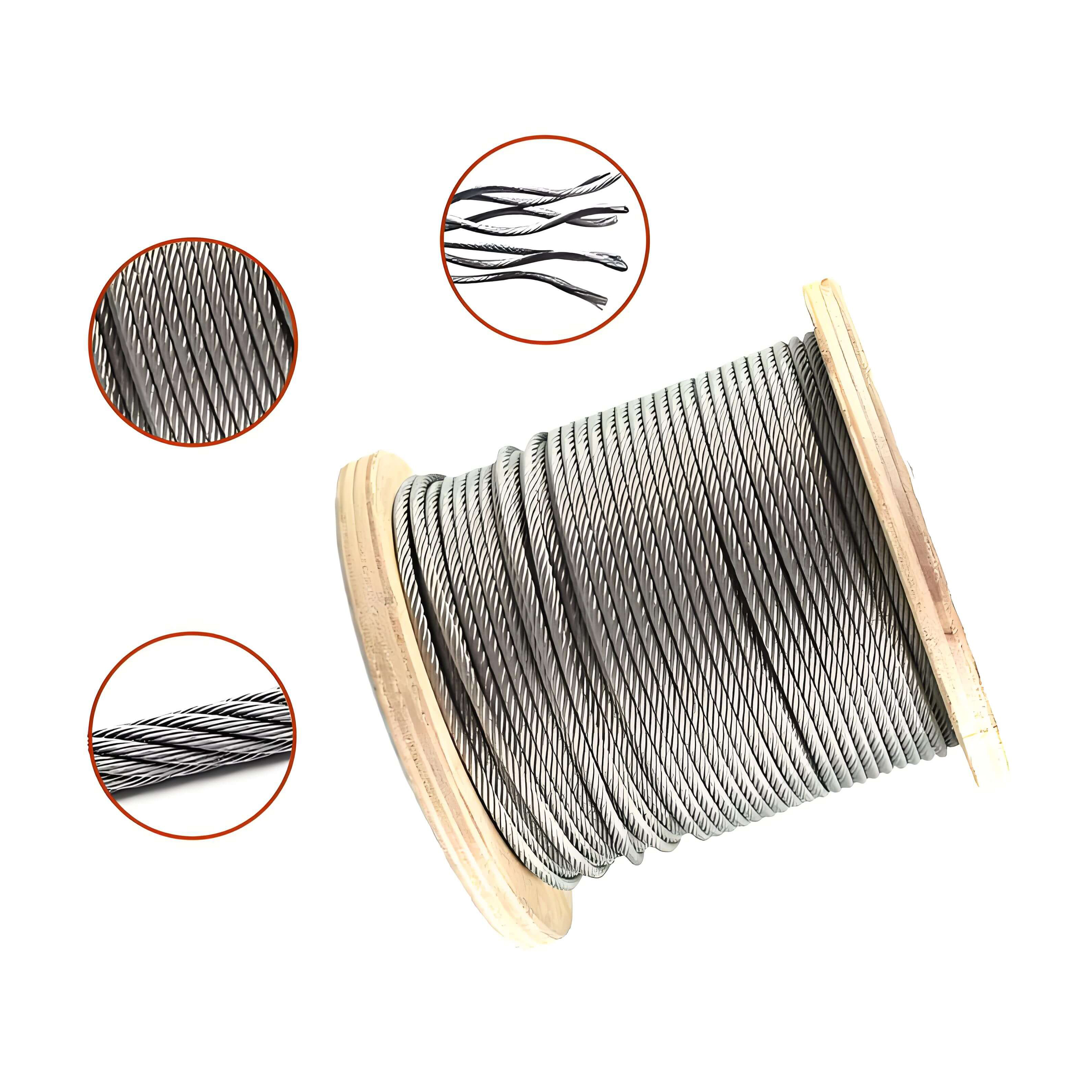
You must also verify your procurement specifications rigorously. When a shipment arrives, confirm the dimensions immediately. Ensure the delivered galvanized steel wire rope matches your exact order. It must align with your specific load parameters. It must meet the dimensional specifications ordered before deployment. Dimensional variations can compromise your expected safety limits. They can alter the breaking strength unexpectedly. A variance of just a few millimeters changes the safety factor entirely.
Establishing a true "zero-hour" baseline is equally critical. You need this baseline for all future safety inspections. This initial un-tensioned diameter provides a crucial reference point. It allows inspectors to accurately calculate future wear rates. Without this baseline, you cannot determine proper retirement criteria later. You risk retiring healthy equipment too early. Worse, you risk leaving degraded equipment in service too long. This zero-hour data anchors your entire preventive maintenance strategy.
Accurate measurements require highly specific industrial tools. You cannot rely on standard tape measures. You must never use standard pointed-jaw calipers. Flat-jaw vernier calipers serve as the absolute industry standard. They provide the precise contact area needed for cylindrical braided structures. Using the wrong tool guarantees compromised data and safety risks.
Standard calipers create a dangerous measurement pitfall known as the "valley" trap. Their narrow, pointed jaws easily slip into the valleys. These valleys exist between individual outer strands. When jaws slip into these gaps, they deliver an inaccurate reading. The reading appears artificially small. You might mistakenly reject a perfectly good delivery. Alternatively, you might install an oversized cable into incompatible sheaves. Flat jaws bridge the gaps between strands effectively. They ensure contact happens only on the outermost crowns.
Tool calibration remains equally vital for compliance auditing. You must use recently calibrated measurement devices. They must be properly zeroed-out before every single use. Every time you handle new steel wire rope, inspect your measuring tools first. Outdated or uncalibrated calipers ruin your compliance auditing standards. Regular calibration checks guarantee your readings reflect reality. Many facilities mandate third-party calibration annually using gauge blocks. They also require field-level zeroing before each shift. This dual-layer approach eliminates instrumental errors entirely. Proper tooling represents a small investment. It pays massive dividends in operational safety.
Following a strict procedure guarantees accurate and repeatable results. You must eliminate guesswork from the measurement process. Haphazard measurements yield conflicting data. Here is the industry-standard method you should follow every single time.
Locate the Measurement Zones: Avoid measuring near the extreme ends. The ends often fray or distort slightly after cutting operations. Select a straight, un-deformed section instead. Ensure the section is free of dirt or heavy debris. Clean the area gently if necessary.
Position the Calipers Correctly: Align the flat jaws perfectly parallel to the longitudinal axis. Proper alignment prevents diagonal skewing. The jaws must touch the outermost limits. These outer limits are called the crowns of opposite strands. Never angle the caliper diagonally across the strands.
Execute the 90-Degree Cross-Measurement: Take your first reading carefully. Record this initial number. Next, rotate the caliper exactly 90 degrees at the exact same location. Take a second reading here. Average these two measurements together. This crucial step accounts for any slight ovalization. Cables often rest in slightly non-circular shapes.
Repeat Across Multiple Points: A single location provides incomplete data. Take measurements at three distinct locations at minimum. Space them at least several feet apart. This spacing confirms manufacturing consistency along the entire length. Average all cross-measurements to find the final baseline diameter.
Industry standards define strict acceptable size ranges. Groups like the American Petroleum Institute (API) and ISO dictate specific design intents. New products must be slightly larger than their nominal diameter. This plus-tolerance typically ranges from +0% to +5%. The exact percentage depends heavily on the nominal size. Manufacturers design them this oversized way deliberately.
Once tension applies, internal dynamics shift. The core compresses under the load. The outer strands seat tightly together. This seating process reduces the overall diameter naturally. If you measure high tensile steel wire rope and find it exactly at nominal size, beware. It will likely become undersized during actual operation. An undersized cable compromises the safety factor. It limits your lifting capacity dangerously.
You need a clear framework for interpreting this data. Compare your averaged readings against equipment safety margins. Your sheave gauges will confirm safe fits. Check the sheave grooves before installation. Ensure the measured plus-tolerance fits the groove safely. If the rope sits too high, the groove is too tight.
Material variables also influence these tolerances significantly. Compacted constructions behave differently than standard round varieties. Compacted strands have flatter outer surfaces. They experience a pre-compression phase during manufacturing. Because of this, they show less initial stretch. They often require tighter tolerance considerations. Standard constructions stretch more noticeably during the initial break-in period.
Standard Allowable Diameter Tolerances Guide
Nominal Diameter Range | Minimum Allowable Tolerance | Maximum Allowable Tolerance |
|---|---|---|
Up to 8mm (5/16") | -0% | +8% |
Over 8mm to 28mm (1-1/8") | -0% | +5% |
Over 28mm (1-1/8") | -0% | +4% |
Even highly experienced technicians make occasional measurement errors. You can prevent skewed data by understanding these common pitfalls. Focus heavily on consistency and proper technique across your team. Eliminate these bad habits to ensure accurate reporting.
Applying Excessive Pressure: Calipers are precision instruments. They are not clamps. Squeezing the jaws too tightly distorts the outer wires. This pressure compresses the structure. It artificially lowers your reading. Use only enough pressure to make solid contact. The caliper should slide smoothly over the crowns.
Measuring Under Full Load: Pre-installation verification serves a highly specific purpose. You must measure un-tensioned or minimal-tension manufacturer baselines. In-service inspections happen under normal operating loads. However, your initial zero-hour check requires a relaxed state. Measuring a loaded cable for a baseline ruins your reference data.
Failing to Document the Baseline: Taking accurate measurements means nothing if you lose the data. This represents a massive management failure. You must record these initial readings in the permanent maintenance log. Do not rely on loose paper or memory. Input the numbers directly into a digital asset management system. This data anchors every future safety inspection.
Ignoring the Wipe-Down Phase: Heavy manufacturing grease often coats new deliveries. This protective grease adds artificial thickness. It can skew diameter readings by fractions of a millimeter. Always wipe the measurement zone clean before applying calipers. This ensures you measure actual steel, not lubricant.
Accurate diameter measurement acts as your primary defense. It prevents premature failure across your heavy lifting operations. It also helps you avoid costly regulatory compliance penalties. Establishing a correct baseline protects both your personnel and your equipment. Proper tooling guarantees reliable data collection. Strict adherence to protocols eliminates human error.
Your immediate next step is clear and actionable. Take your averaged, verified pre-installation diameter readings today. Log them directly into your facility's asset management system. Attach these records to the specific equipment serial number. This recorded data serves as the critical baseline. It anchors all future safety inspections. You can track wear rates accurately over time. You can schedule proactive replacements before dangerous failures occur.
A: Manufacturers build these products with a plus-tolerance, never a minus-tolerance. During initial loading, the core compresses and the strands seat firmly together. This natural process reduces the diameter. Starting slightly oversized ensures the rope settles perfectly into its optimal working dimension.
A: No. Standard micrometers feature small contact faces. These small faces inevitably fall into the gaps between the strands. This provides an inaccurate, undersized reading. You must use flat-jaw measurement tools to accurately capture the outermost circumscribed circle.
A: Take post-installation measurements immediately after the initial break-in period. This captures the seated dimension. Afterward, align your checks with regulatory inspection cycles. Depending on usage severity, you should track continuous wear either monthly or annually.
A: The core principle remains identical. You must always measure the outermost circumscribed circle across the crowns. However, identifying opposite crowns proves visually trickier on odd-numbered strand constructions. This requires extra care when positioning the flat jaws.


